What was SPACERAD?
Above the atmosphere there is nothing to stop the protons and heavy ions streaming through space. When one of them strikes a microchip it can flip a single bit in memory, corrupt a calculation, or latch up a transistor so hard that the chip destroys itself. A satellite cannot be repaired in orbit, so its electronics have to be broken on the ground first—deliberately, and under control.
SPACERAD built the facility to do exactly that. Between 2025 and July 2026 we designed, built and validated a universal experimental platform for Radiation Hardness Assurance testing of microelectronic devices and integrated circuits destined for space, installed on a dedicated beamline of our EMMAS 3 MV Tandetron.
The platform delivers controlled irradiation, dosimetric characterisation and live beam monitoring—and, just as importantly, it comes with a written protocol that tells you how to use it. Both were proven on real flight-candidate hardware from the CARD-SAT nano-satellite, lifting the system from TRL 3 to TRL 4: technology validated in a laboratory environment.
At a glance
- Full title: An Innovative Ion Irradiation Platform for Exploring Nano-Satellites Resilience to Space Radiation
- Programme: PN-IV-P7-7.1-PED-2024-2029
- Contract: 53 PED/2025
- Ran: 2025 – 31 July 2026
- Host facility: EMMAS 3 MV Tandetron, IFIN-HH
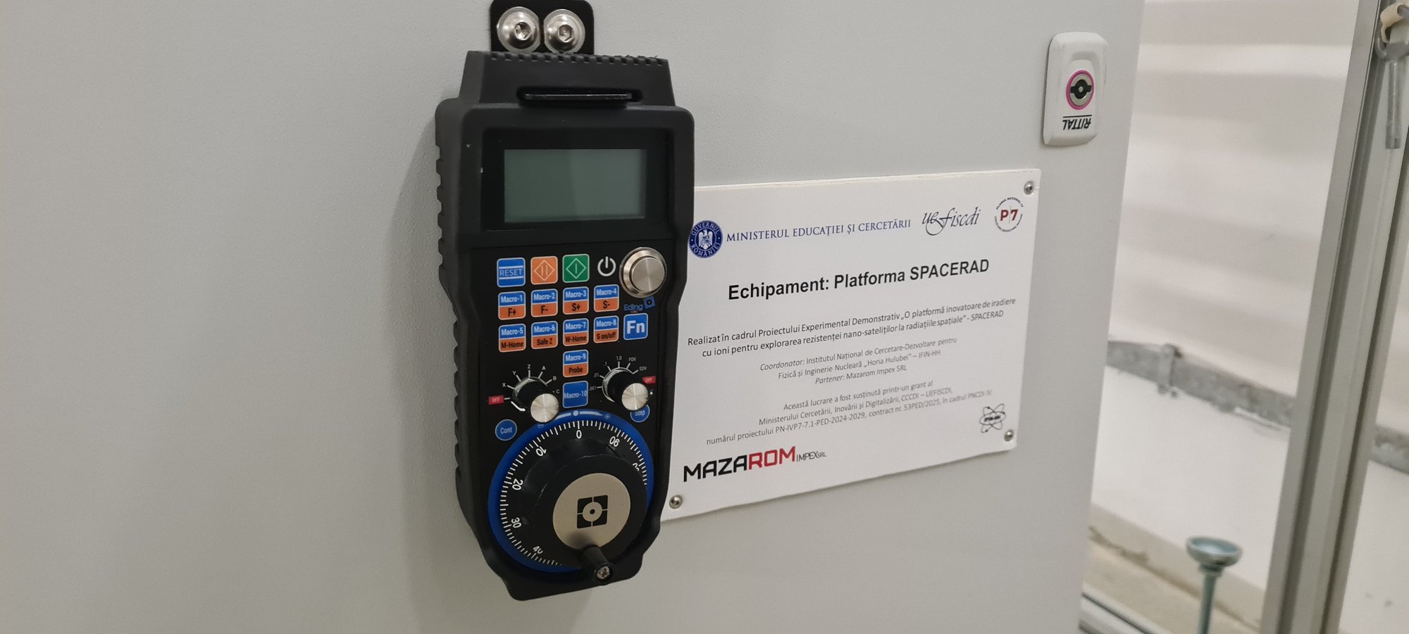
- Industrial partner: MAZAROM Impex
- Maturity reached: TRL 3 → TRL 4
The platform
A proton beam brought out into open air, and a robot that puts your chip exactly where it lands
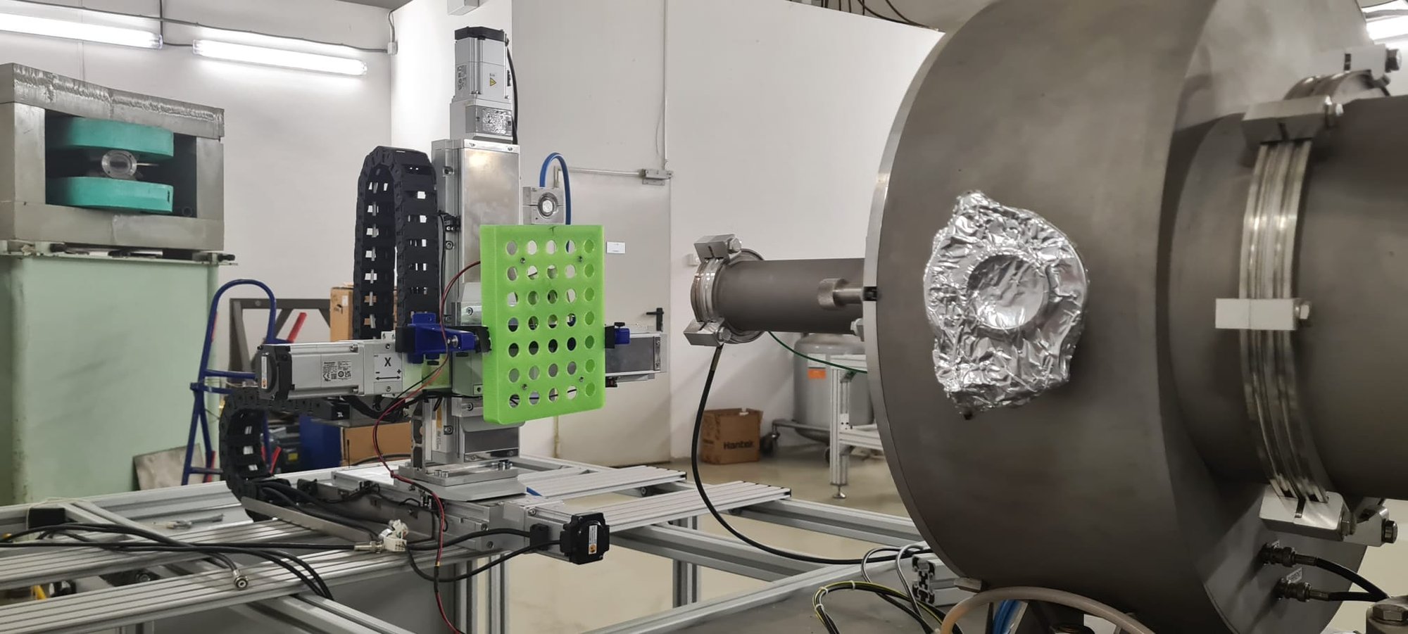
The heart of SPACERAD is a three-axis micrometric positioning system, designed in CAD and built together with our industrial partner MAZAROM. A test board is clamped to the stage, and an alignment laser correlated with the mechanics centres the exposed die—or rather, the slit in its mask—on the central axis of the proton beam.
Unlike most irradiation experiments, the beam here is extracted into air through a thin window. That is a deliberate choice: it means a populated circuit board, with its connectors and cabling still attached, can be tested live while it runs its own firmware, without having to survive a vacuum chamber first.
Getting there took beam-optics simulations to optimise ion transport, FLUKA simulations of the dose distribution across the 3–6 MeV proton range, mechanical and optical alignment of the beam-scattering foil, and high-vacuum testing of the upstream line.
Knowing the dose
A radiation test is only worth as much as its dosimetry
Saying that a chip survived "a proton beam" means nothing on its own. To compare a laboratory result against a real orbit, you have to know the energy, the flux, the accumulated fluence, the dose rate and how evenly the beam was spread across the die. SPACERAD measures all of them, with deliberately redundant instruments:
- Markus ionisation chamber — the primary dose monitor. Cumulative dose is reconstructed from the monitored current and the exposure time.
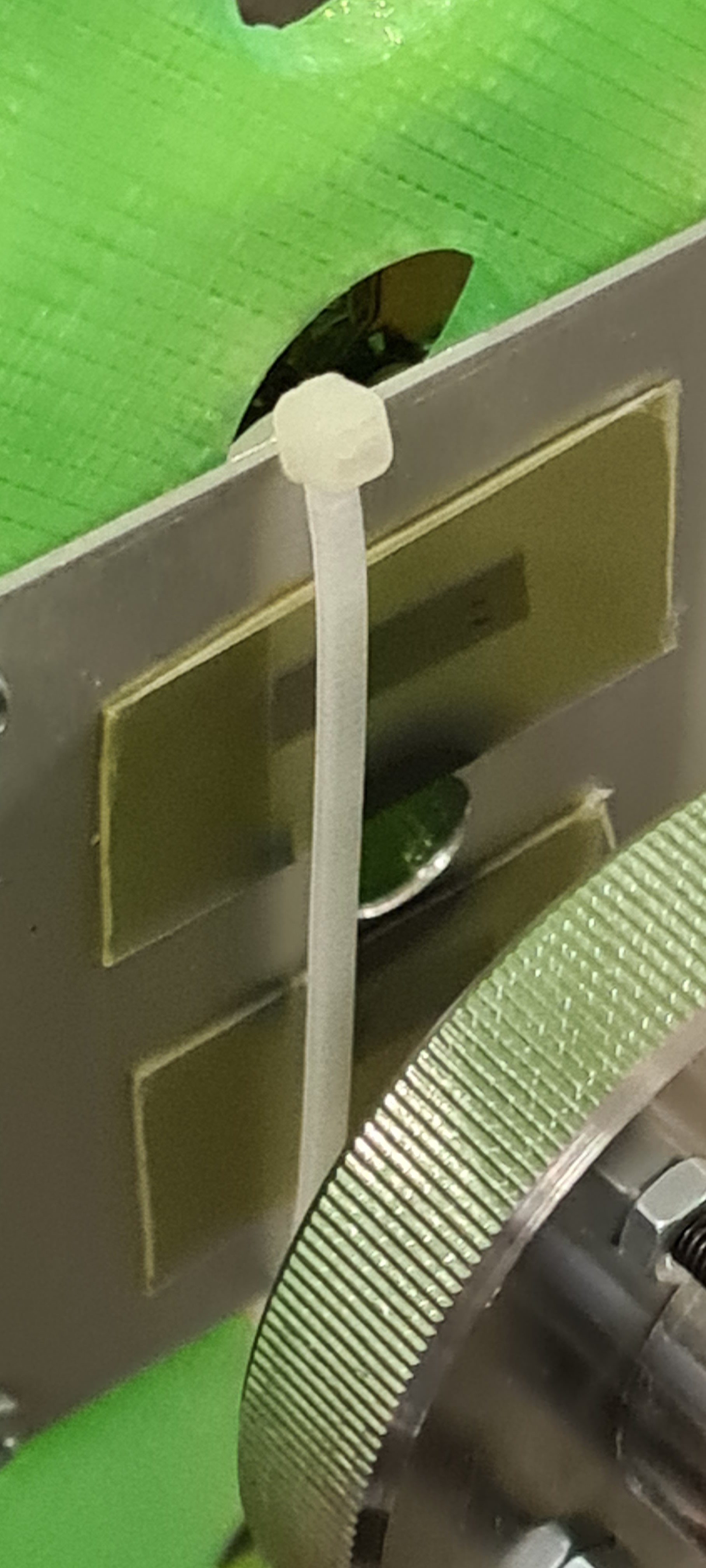
- Radiochromic films — they darken in proportion to dose, giving a permanent two-dimensional picture of where the beam actually went and how uniform it was.
- Faraday cup and particle detectors — for direct beam current and flux diagnostics upstream.
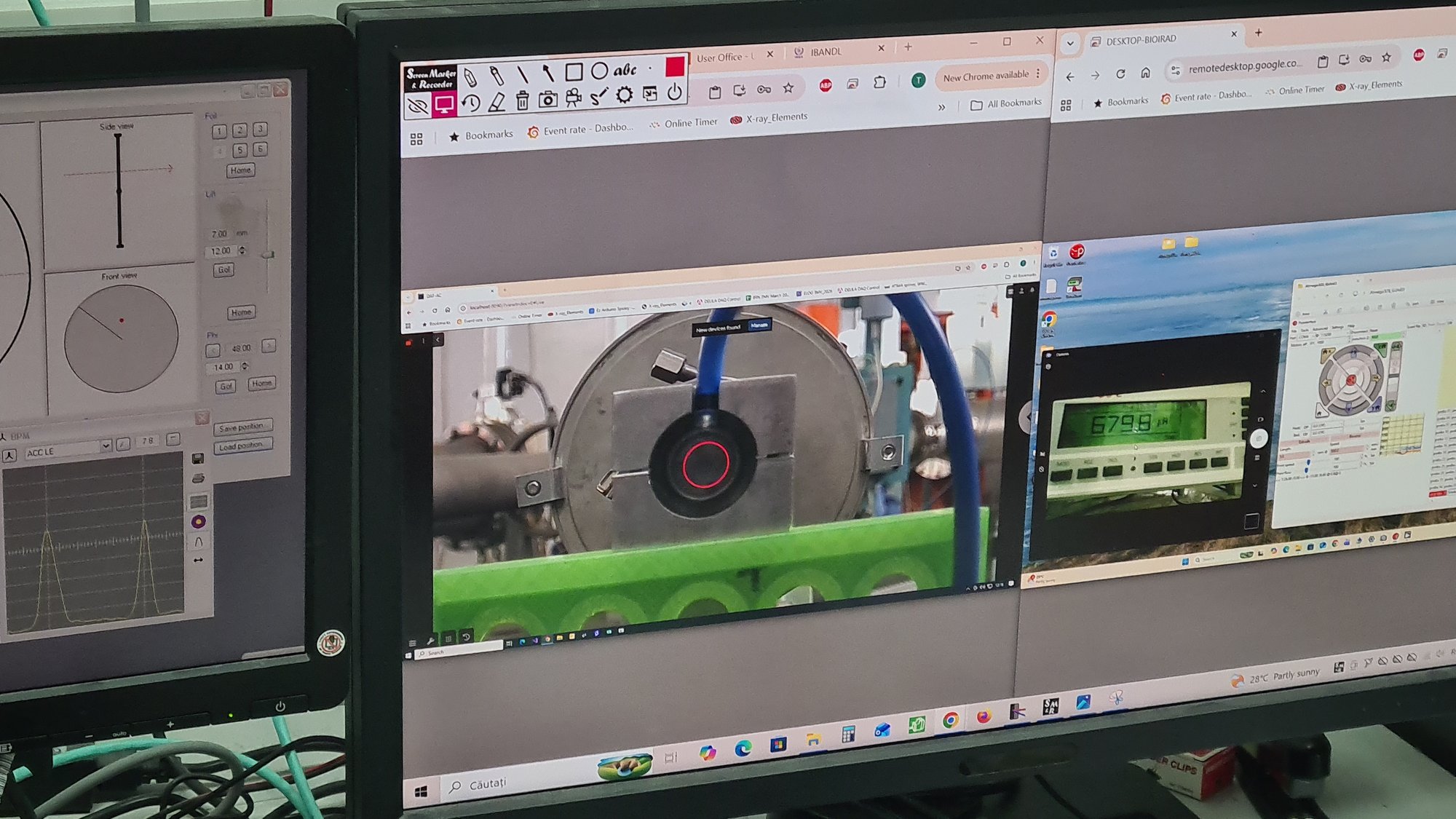
- Thermal imaging camera — watching the component itself for the sudden temperature rise that betrays a latch-up.
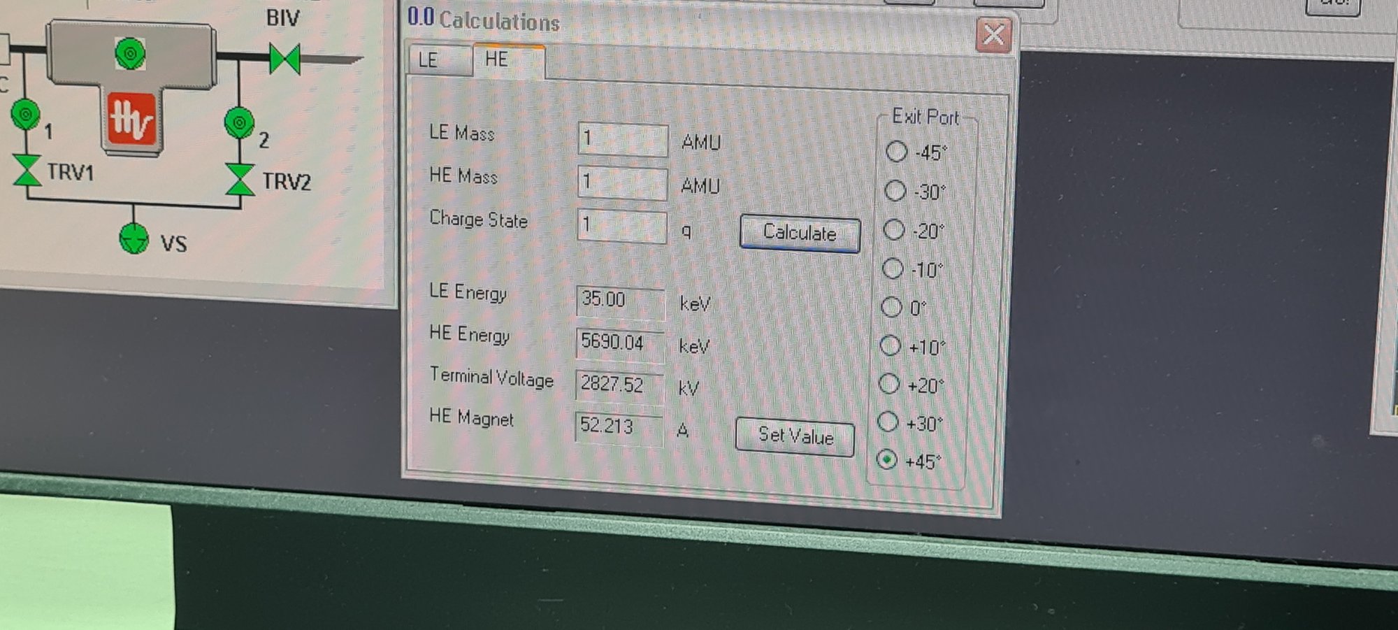
Commissioning ran the extracted proton beam onto the Markus chamber first, then onto radiochromic films, silicon single crystals and radiation-resistant polymer films.
A universal test protocol
The second deliverable, and arguably the more portable one
Hardware alone does not make a testing service. One of SPACERAD's main outputs is a written, reusable protocol for proton testing of nano-satellite electronics—covering total ionising dose (TID), single event effects (SEE), parametric drift under irradiation, the point at which a part stops working, and how it fails. It is summarised here; the full text is in the project reports.
1Identify and document
For every component: part code, manufacturer, batch, fabrication technology, date of manufacture, and its function aboard the satellite.
2Decapsulate—carefully
Protons of 2.5–5 MeV stop within tens to hundreds of micrometres, so a chip under a millimetre of epoxy would never see the beam. The resin is removed chemically or mechanically over the die only, avoiding the bond wires, with X-ray tomography used to check the process before, during and after. Photographs are taken at every stage.
3Mask the board
An individual high-density mask—tungsten, tantalum or lead, thick enough to stop 5 MeV protons outright, or 3D-printed polyethylene where that suffices—exposes one slit above the target die and shields every neighbouring passive and bond pin.
4Characterise before
Nominal parameters hot and cold: supply currents, sensor accuracy, clock frequency, consumption, Flash and SRAM integrity—then a full functional test, a self-test and a benchmark. A minimum of two to three parts per component type are irradiated, plus an un-irradiated control.
5Align, then irradiate
The board is mounted on the three-axis stage and laser-aligned to the beam axis. Data acquisition starts before the beam does: the component runs a functional test in a continuous loop, and only then is the Faraday cup withdrawn to let the protons through.
6Watch, and know when to stop
If the thermal camera sees the part jump more than 15 °C above ambient—the signature of a permanent single-event latch-up—power is cut immediately to stop the silicon cooking itself.
Three standard beam profiles
Depending on the target orbit (LEO or MEO) and on what you are trying to learn about the part, the platform is configured to one of three profiles:
| Profile | Beam energy | Ion flux | Dose rate | Main objective |
|---|---|---|---|---|
| 1 | 5 MeV | 106–107 p/cm2·s | 1–10 Gy/min | Cumulative parametric degradation over time (charge trapped in the oxides). |
| 2 | 2.5–5 MeV | 108–1010 p/cm2·s | 10–100 Gy/min | Transient errors—bit-flips in SRAM, logic lock-ups in the microcontroller. |
| 3 | 5 MeV | 1011 p/cm2·s | ≥ 700 Gy/min | The critical threshold for physical destruction and thermal burnout. |
Afterwards
The beam going off is not the end of the test. The component is held under power at room temperature for 24, 48 and 72 hours to see whether the parametric damage the protons caused is permanent or partially self-repairs—an annealing test. A follow-up micro-CT scan then looks for micro-cracks or delamination induced by the higher dose rates. Where live monitoring is impractical, the whole electrical characterisation can equally be done offline afterwards. Every campaign ends in a report carrying the platform description, proton energy, flux, fluence, dose rate, beam distribution, radiochromic film images, sample photographs, electrical and functional results, SEE statistics, failure thresholds and conclusions.
Proving it on real satellite hardware
CARD-SAT electronics, live in the beam
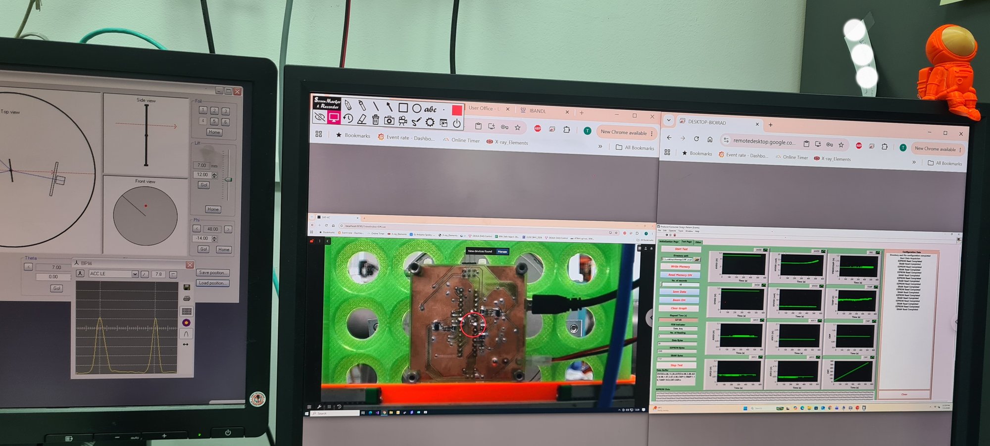
A platform is only validated when something real goes through it. The final stage of the project put components from the CARD-SAT nano-satellite into a 5 MeV proton beam and monitored their response in real time under extreme conditions of dose and flux.
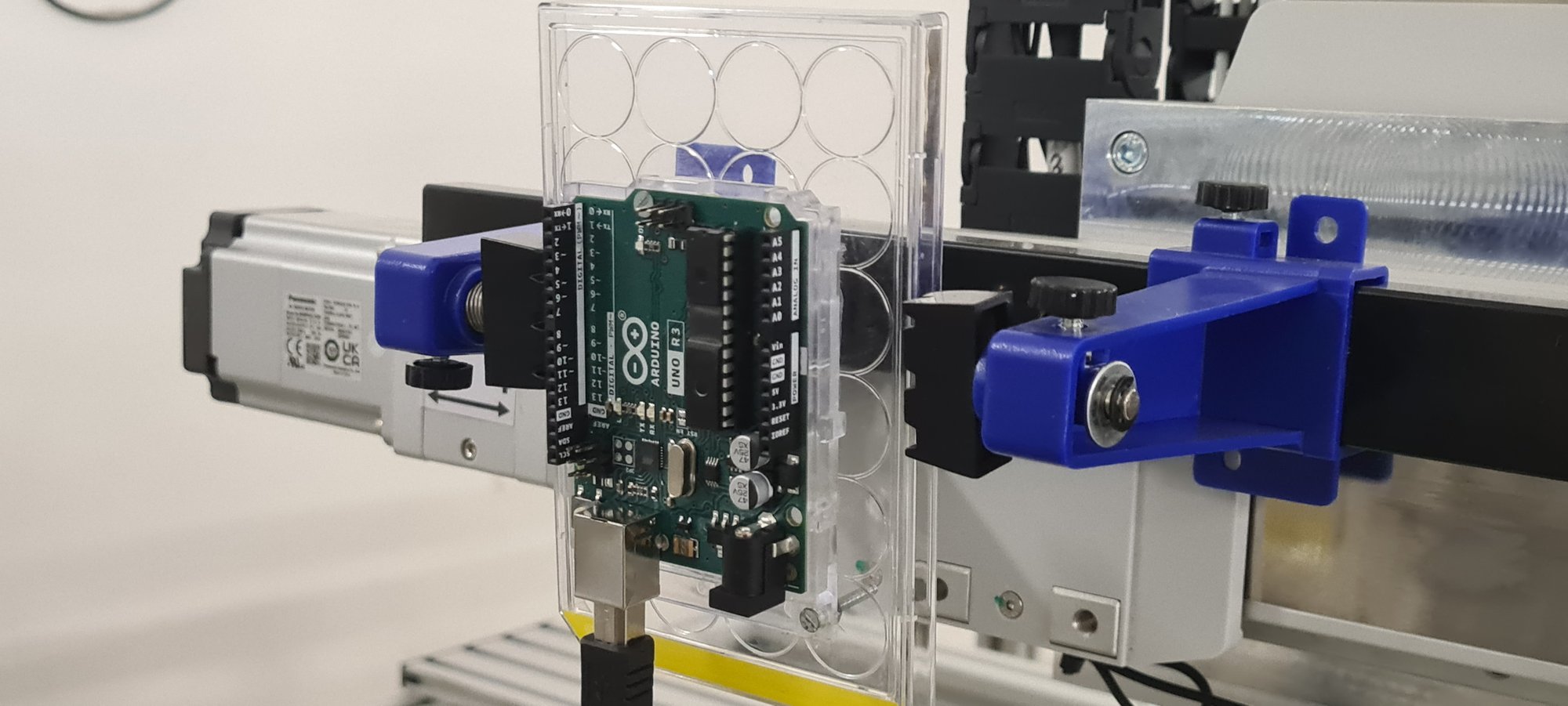
The first part on the stage was the ATmega328P-AU—the 8-bit Microchip microcontroller CARD-SAT flies, and, as it happens, the same chip at the heart of the Arduino Uno. If you have ever built anything on an Arduino, you have held the part we shot protons at. (We use its relatives for teaching too, in our build-your-own accelerator.) Temperature sensors such as the MCP9808 followed.
Devices were micro-CT scanned before and after irradiation—a non-destructive way to hunt for micro-cracks from the ion impact, to assess damage to bond wires and interconnects, and to confirm that the epoxy decapsulation had actually reached the die. At the doses we used, the CT scans showed no structural change to the components.
Results & dissemination
Papers, conferences and public reports
Publications
- A.T. Hotnog, M. Petruneac, M. Focșăneanu, R.F. Andrei, M. Lechințan, D.A. Iancu, D.G. Ghiță, G. Velișa, M. Straticiuc, A. Totu, C. Gogu, I. Burducea, Design and Implementation of an Ion Irradiation Platform for Radiation Hardness Testing at the 3 MV TandetronTM from IFIN-HH, Romanian Journal of Physics 71, 303 (2026).
- Damage and recovery in crystalline silicon under complex irradiation spectrum, Nuclear Instruments and Methods in Physics Research B — under peer review, 2026.
Conferences
- IBMM-24 — 24th International Conference on Ion Beam Modification of Materials, Helsinki, Finland, June 2026. Sequential Proton and Heavy-Ion Irradiation of Si and Ge Crystals: Toward a Radiation Hardness Testing Platform for Microelectronic Devices (poster).
- ECAART 15 — 15th European Conference on Accelerators in Applied Research and Technology, Zurich, Switzerland, September 2025. A novel radiation hardness testing facility at the 3 MV Tandetron from IFIN-HH — status report.
- BPU 12 — 12th International Congress of the Balkan Physical Union, Bucharest, July 2025. FLUKA simulations for the optimisation of an ion irradiation platform for radiation hardness studies.
- Bucharest University Faculty of Physics Meeting 2026, Măgurele, May 2026 — Current status of the Innovative Ion Irradiation Platform (oral).
Official project reports
The full result summaries and publication list, as submitted to the funding body:
Beyond the project
Work to push the platform past TRL 4 is already under way:
- MAZAROM exhibited the SPACERAD platform at Metal Show & TIB 2026, Bucharest, 12–15 May 2026.
- Two working visits to ROSA, the Romanian Space Agency.
- Participation in ESA funding information sessions in 2025 and 2026 at UNSTPB.
- A follow-on proposal on standards-based radiation dosimetry for space technologies, submitted to the ELI-RO C1 2025 call.
Open Day at the Tandetron
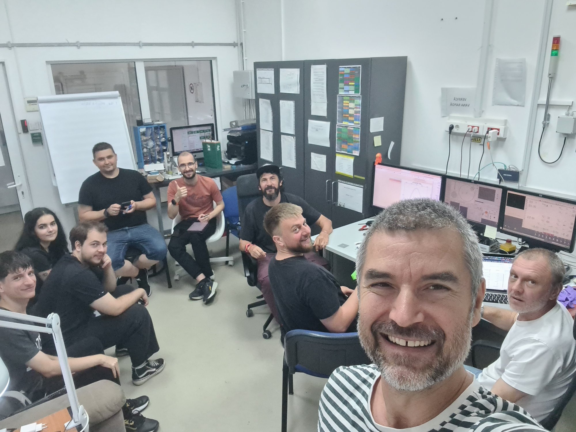
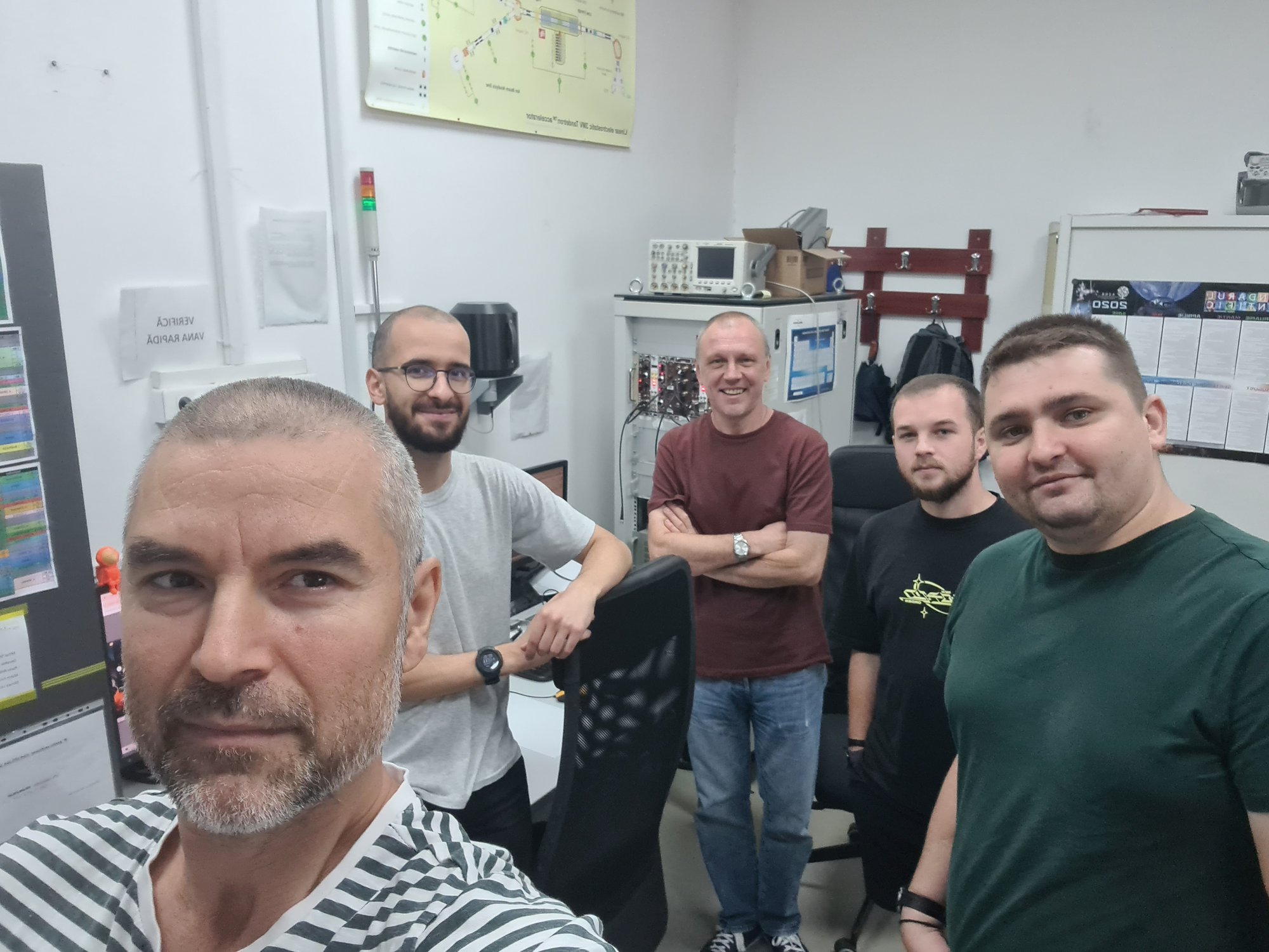
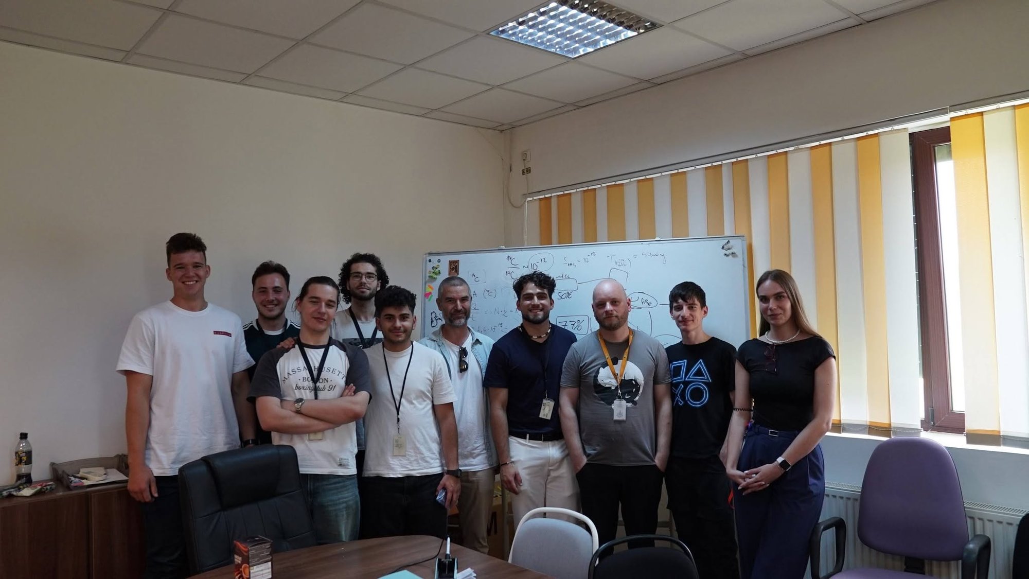
In June 2026 the group opened its doors for a day to ten physics and engineering students—seven first-years and three master's students from the Faculty of Physics. They toured the 3 MV Tandetron, heard how the project works, and then sat down to a genuinely hands-on task: soldering capacitors, resistors and a microcontroller onto a bare PCB, which, if everything went in the right way round, came to life as a working digital clock.
The deliberately small group meant everyone got real time with the equipment. Several students went away asking about internships with us, which was rather the point. If that sounds like you, our students page explains how to apply—and you can practise on the virtual control room before you arrive.
SPACERAD in pictures
Building the platform, running the campaigns, and the people who did it
The team
IFIN-HH
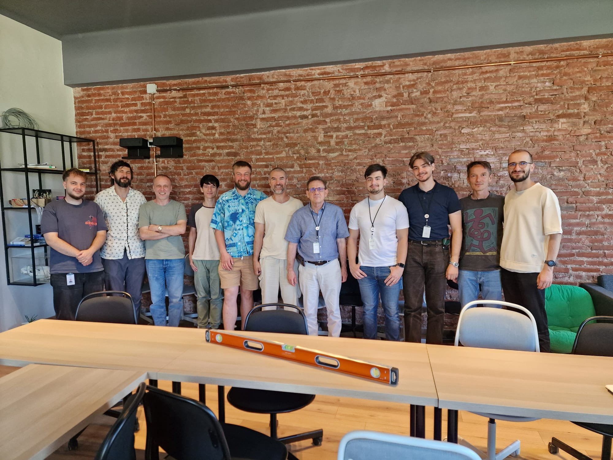
Ion Burducea, Marta Petruneac, Decebal-Alexandru Iancu, Mihai Straticiuc, Gihan Velișa, Dan Gabriel Ghiță, Andrei-Theodor Hotnog, Mircea Lechințan, Radu Florin Andrei, Marin Focșăneanu.
MAZAROM Impex
Adrian Totu, Cosmin Gogu, Marius-Constantin Simion, et al.
Project enquiries: bion [at] nipne.ro
SPACERAD was funded through the Romanian national programme PN-IV-P7-7.1-PED-2024-2029, contract 53 PED/2025.
Talk to us about testing your hardware