A working model of the real thing
Open hardware that turns particle acceleration into something you can watch
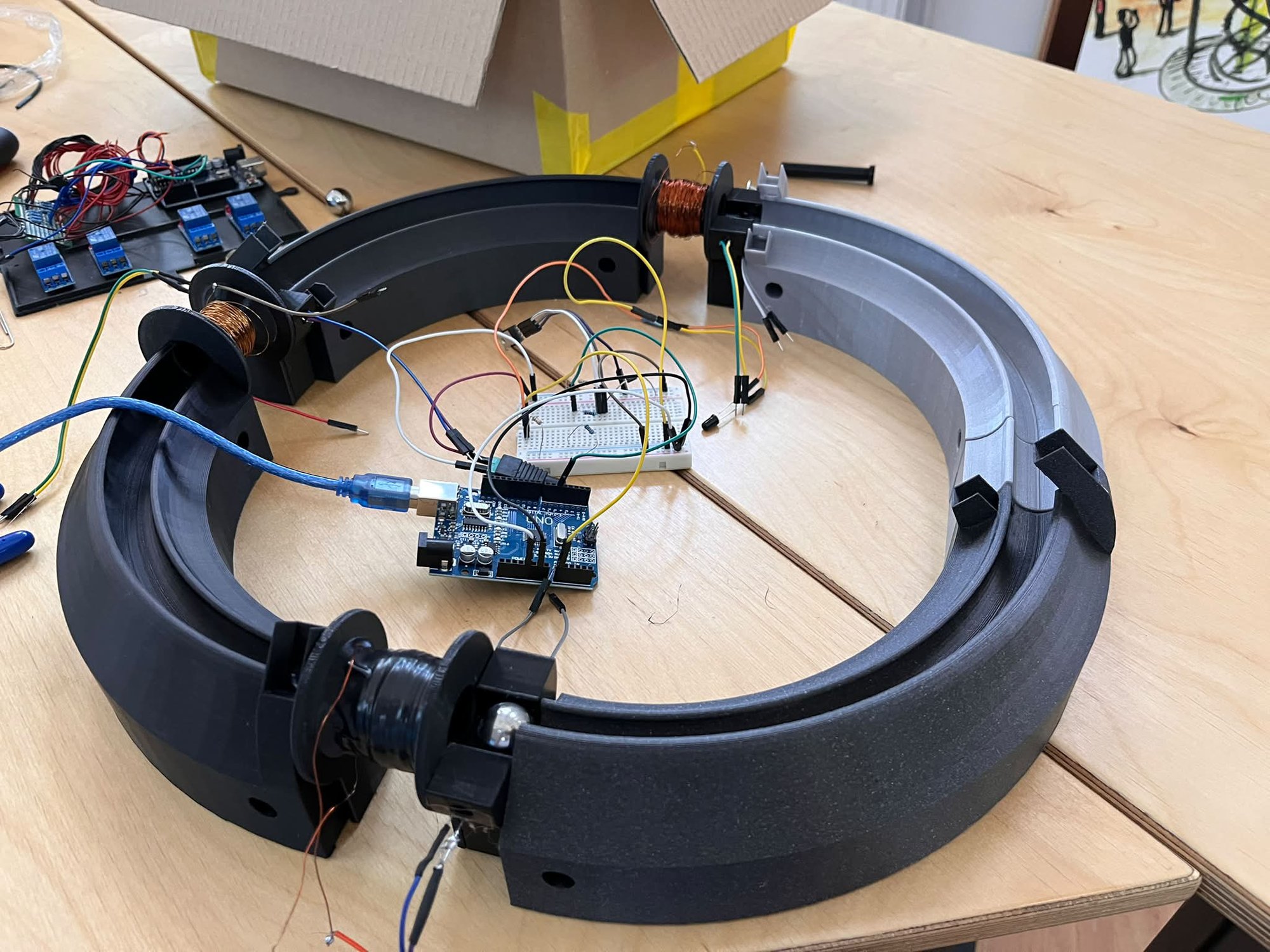
The accelerators down the hall at DFNA are large, shielded and impossible to open up in front of a curious visitor. This desktop model shows the same core idea in miniature: use precisely-timed electromagnets to accelerate a projectile, one stage at a time.
Built in-house with 3D printing, CNC machining and an Arduino, it turns an abstract concept into something children and adults can watch, touch and understand in a few seconds — then ask the questions that lead to the real physics.
It is designed as open hardware: every part, the wiring, the 3D models and the control code are documented so that a school, a student or a hobbyist can rebuild it. It travels with us to science fairs and school events such as the ReCoNnect Science Caravan.
How it works
Sense the ball, fire the coil, repeat — the staged-acceleration principle
A small ferromagnetic ball runs along a track lined with electromagnetic coils. As the ball approaches a coil, an optical barrier — an infrared LED facing a phototransistor — detects it, and the Arduino switches that coil on for a few milliseconds through a MOSFET. The magnetic field pulls the ball in.
The trick is timing: the coil is switched off the instant the ball reaches its centre, so the pull is always forward and never backward. Each stage adds a little more speed — exactly the staged principle that real linear and tandem accelerators use to reach high energies.
The control loop, per stage
The 2026 rebuild
A faster, more reliable, more reproducible version
The latest iteration keeps only the ball guides from the earlier version — the electronics were redesigned from scratch, and the mechanics reworked so that others can reproduce the build reliably.
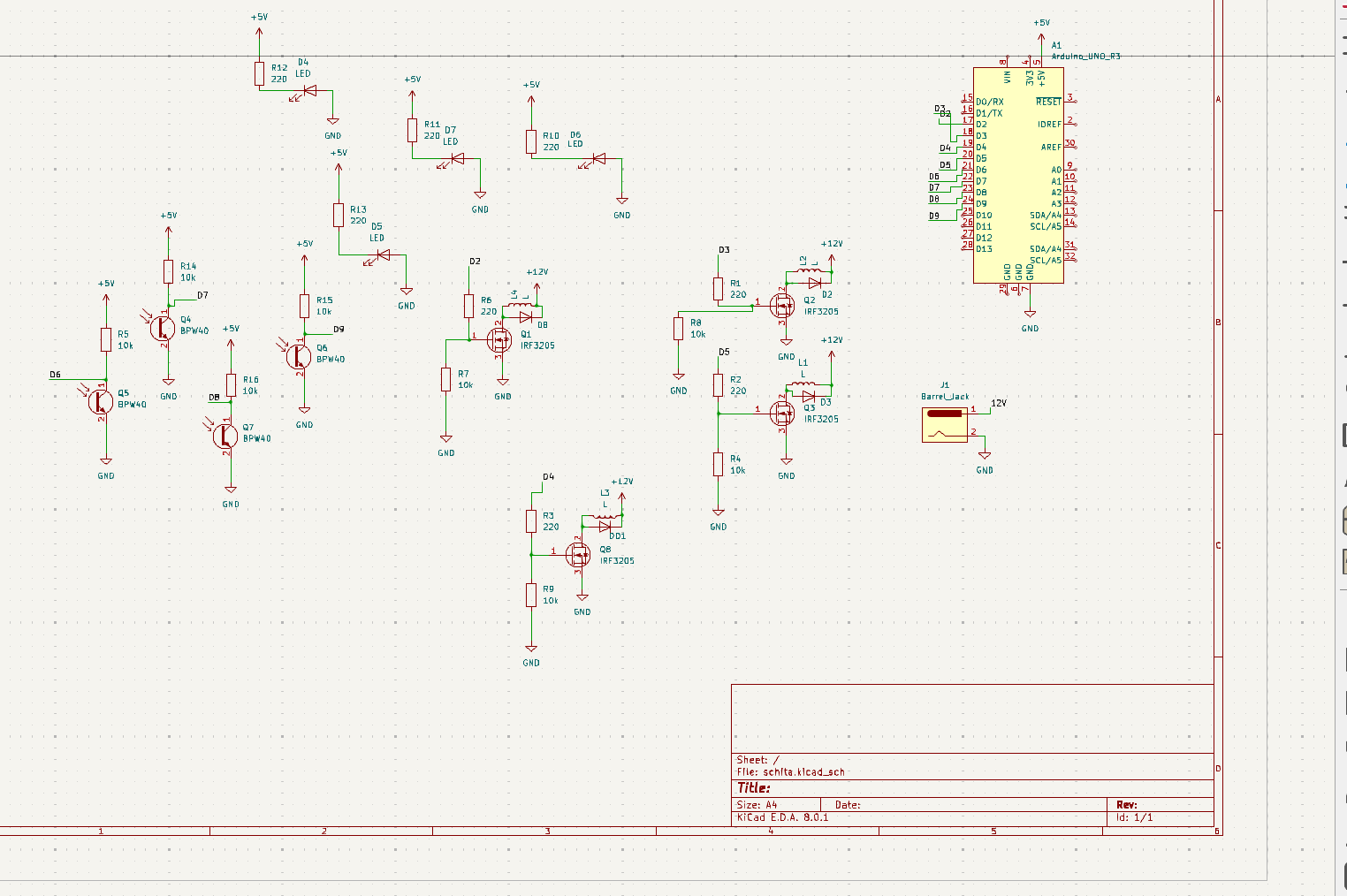
- Relays → MOSFETs. The old 5 V relay switching was replaced with MOSFET transistors, allowing higher coil voltages and currents and much faster, more efficient switching.
- Optical barriers for timing. Each stage uses an infrared LED and a phototransistor to detect the ball precisely and synchronise when its coil fires.
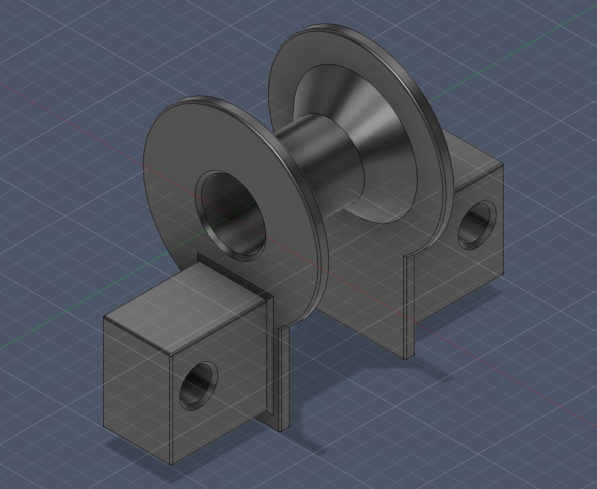
- Redesigned mechanics. New printed mounts for the optical barriers and a new support system for the electromagnetic coils.
- Reproducible coil winding. An improved winding technique that is easier to repeat consistently across builds.
- Documented for replication. A complete bill of materials, wiring, 3D models and code — so the design keeps improving from one version to the next.
At a glance
- Three-stage electromagnetic (coil) accelerator.
- 18 mm ferromagnetic ball as the projectile.
- Arduino Uno R3 control; 3× IRF3205 MOSFET coil drivers.
- Four IR optical barriers (BPW40 phototransistors).
- ~20 ms coil pulse per stage; 12 V / 2 A supply.
- 3D-printed structure; designed in KiCad, Arduino IDE & PrusaSlicer.
Open documentation
Everything you need to rebuild it — free to use for education
How to build it
Hardware — bill of materials
| # | Component | Qty | Purpose |
|---|---|---|---|
| 1 | Arduino Uno R3 | 1 | Control unit |
| 2 | MOSFET IRF3205 | 3 | Coil drivers |
| 3 | Electromagnetic coil | 3 | Acceleration stages |
| 4 | Phototransistor BPW40 | 4 | Projectile detection |
| 5 | IR LED | 4 | Optical barriers |
| 6 | Resistor 220 Ω | 7 | Current limiting |
| 7 | Resistor 10 kΩ | 7 | Biasing |
| 8 | Power supply 12 V / 2 A | 1 | System power |
| 9 | Ferromagnetic ball, 18 mm | 1 | Projectile |
| 10 | 3D-printed frame | 1 | Mechanical structure |
| 11 | Wires & connectors | — | Interconnects |
Software & tools
- Arduino IDE — firmware development & upload (free)
- KiCad 8 — electronic schematic (open source)
- Cura / PrusaSlicer — slicing the 3D-printed parts
Wiring schematic
Control code (Arduino)
The sketch continuously reads the optical barriers; when a sensor detects the ball, its coil is energised for about 20 ms, then released before the ball reaches the coil centre. Example logic for the three stages:
const int mosfetPins[] = {5, 6, 7};
const int numarEtaje = 3;
const int prag = 200;
const int impulsMs = 20;

void setup() {
  Serial.begin(9600);
  for (int i = 0; i < numarEtaje; i++) {
    pinMode(mosfetPins[i], OUTPUT);
    digitalWrite(mosfetPins[i], LOW);
  }
}

void loop() {
  for (int i = 0; i < numarEtaje; i++) {
    int valoare = analogRead(senzoriIR[i]);
    Serial.print("Senzor ");
    Serial.print(i + 1);
    Serial.print(": ");
    Serial.println(valoare);
    if (valoare > prag) {
      digitalWrite(mosfetPins[i], HIGH);
      delay(impulsMs);
      digitalWrite(mosfetPins[i], LOW);
      while (analogRead(senzoriIR[i]) > prag) {
        delay(10);
      }
    }
  }
}
Excerpt from the project documentation. The full sketch, KiCad schematic and printable STL files are available for schools and educational projects — get in touch.
Bring the physics to your event
The accelerator model is part of DFNA's outreach toolkit — a way to start a conversation about accelerators, magnetism and nuclear science with visitors of every age. We bring it to school visits, science fairs and events like the ReCoNnect Science Caravan.
Want a demonstration, or the plans to build your own? We would love to hear from you.
Our outreach Get in touchBuilt at DFNA with
- 3D printing
- CNC machining
- Arduino & open electronics