Specs at a glance
Key parameters of the EMMAS 3 MV Tandetron
| Manufacturer | High Voltage Engineering Europe (HVEE) |
|---|---|
| Commissioned | 2012 |
| Type | Tandem electrostatic accelerator (TandetronTM), terminal mid-column |
| Terminal voltage | Up to 3 MV |
| Insulating gas | SF6 at ~6 bar |
| Column vacuum | 10−7–10−5 mbar |
| Ion sources | 860A Cs sputter (negative ions) + 358 duoplasmatron |
| Beam lines | Three — IBA, implantation/irradiation, cross-section measurements |
| Switching magnet | Ports at 10°, 20°, 30°, 45°; 0° Faraday cup |
| IBA techniques | RBS, RBS/C, ERDA, PIXE, PIGE |
| Applications | Ion beam analysis, ion implantation, radiation testing, cross-section measurements |
What it is
A versatile ion-beam accelerator for applied research
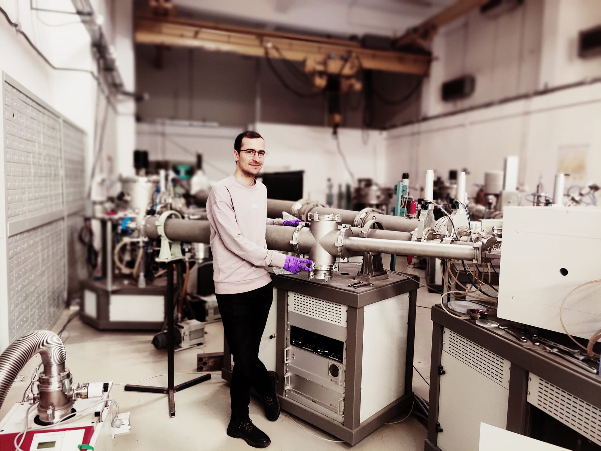
Point a beam of fast ions at a material and it gives up its secrets — what it’s made of, how it’s layered, how it stands up to radiation. Doing that, reliably and across many fields, is this machine’s day job. The 3 MV Tandetron accelerator, manufactured by High Voltage Engineering Europe (HVEE), was installed and commissioned in 2012 and is mainly dedicated to applied research. It is fully equipped for studies with accelerated ion beams: Ion Beam Analysis (IBA), ion implantation (IIB), radiation-resistance testing of advanced materials, and cross-section measurements (CSM) of nuclear-astrophysics interest.
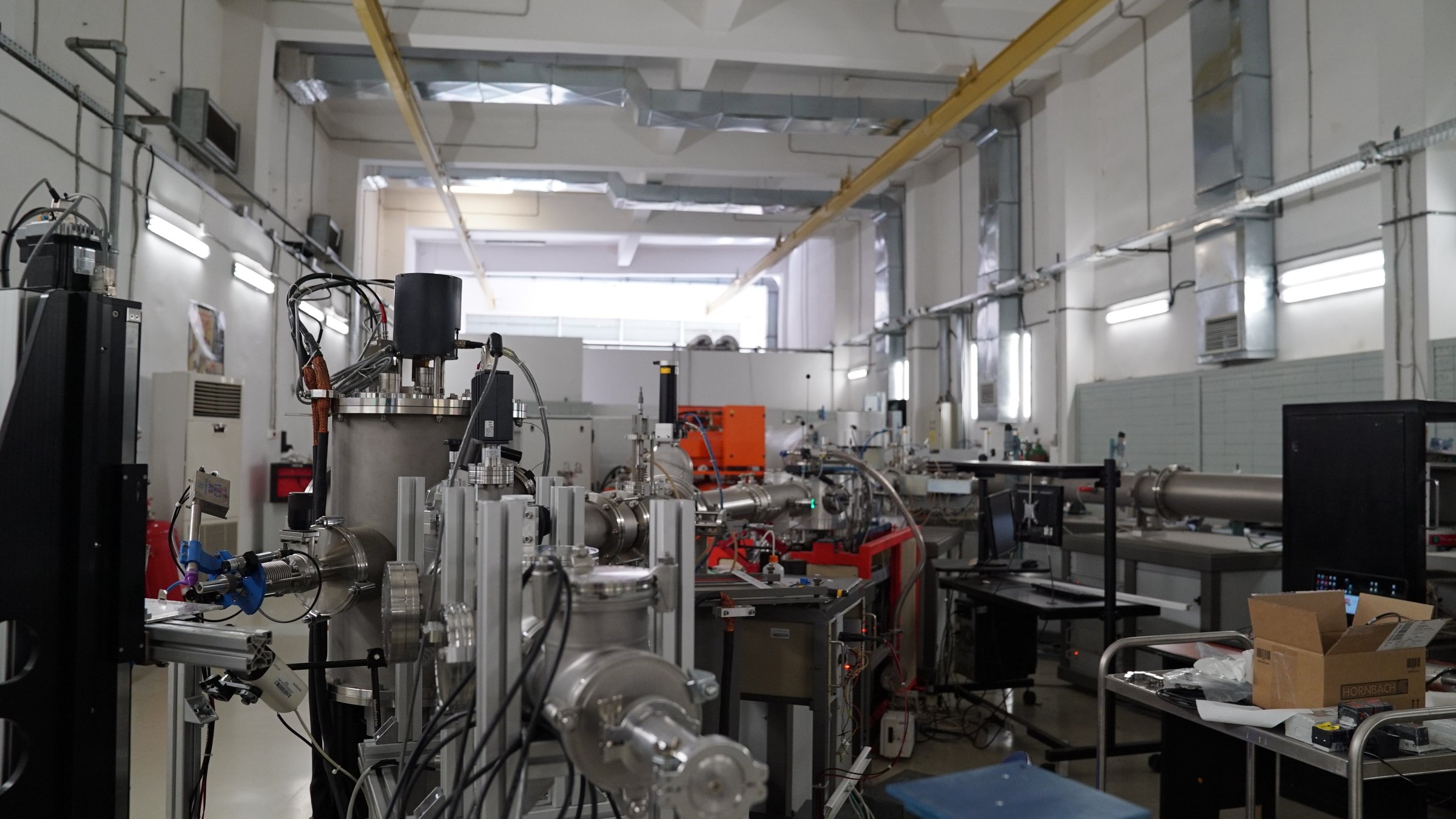
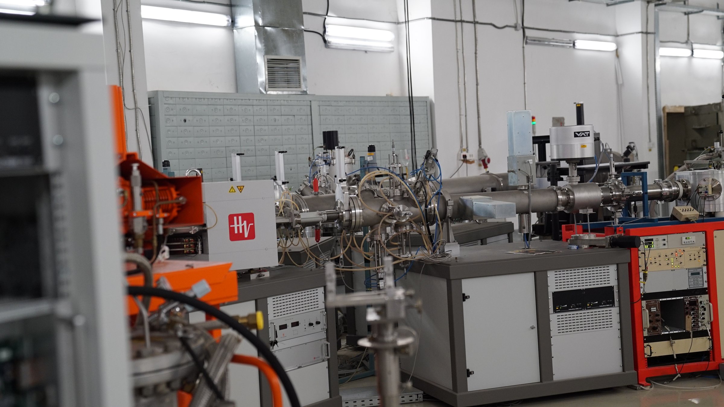
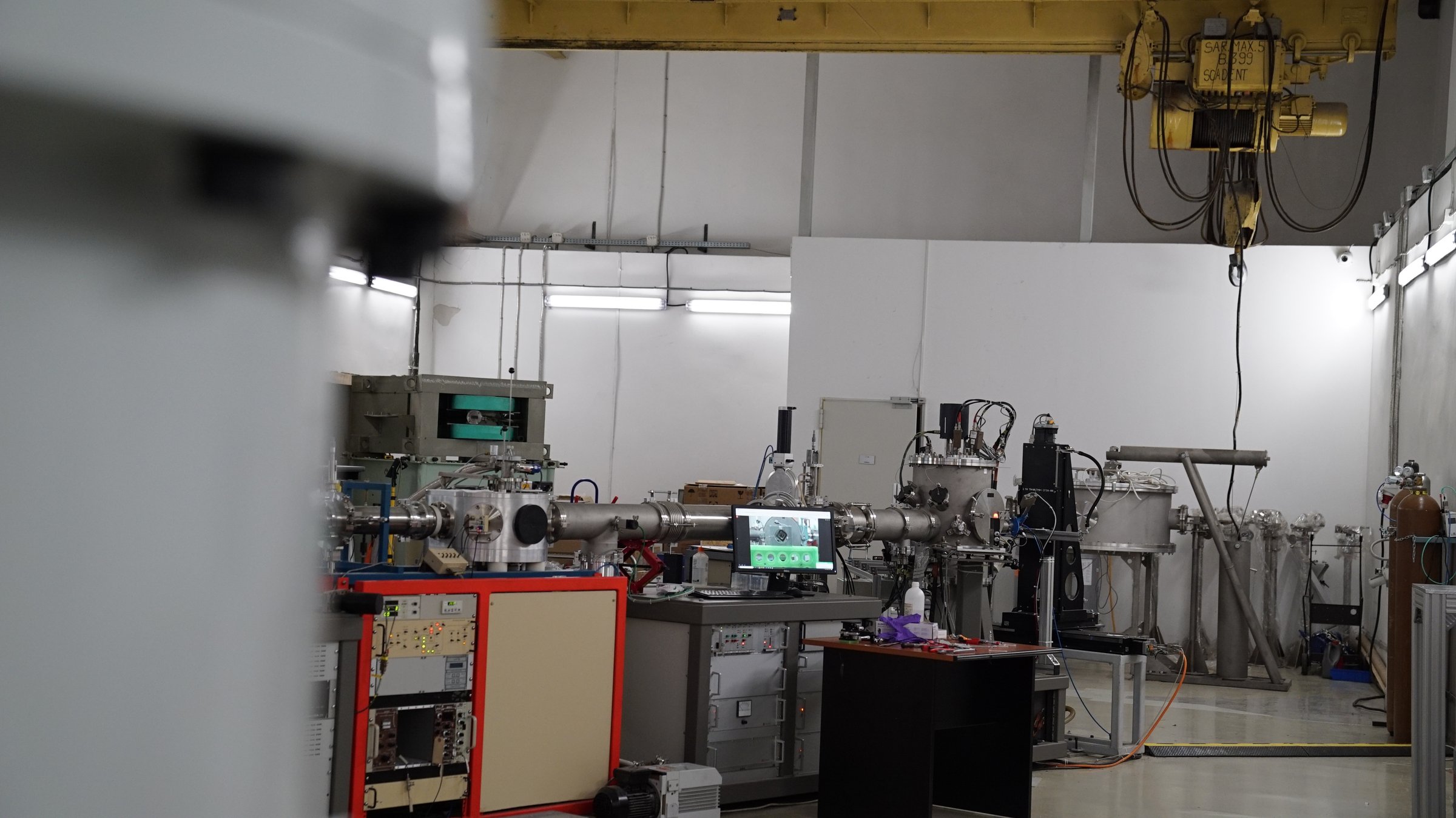
The system provides three experimental beam-lines, each with a reaction chamber and the diagnostics and data-acquisition equipment they need.
As a tandem accelerator, the high voltage sits at a terminal mid-column with both ends at ground; the acceleration column is enclosed in a tank of sulfur hexafluoride (SF6) at ~6 bar, whose dielectric strength (about 2.5× that of air) suppresses micro-discharges and lets the machine hold up to 3 MV.
Inside the machine
The acceleration column and how the high voltage is held
The SF6 in the tank does more than insulate: being strongly electronegative, it captures the free electrons from micro-discharges before they can avalanche.
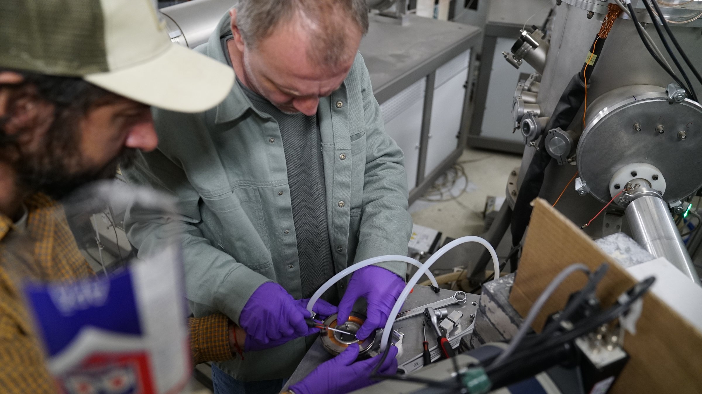
Inside, each of the two acceleration sections is built from alternating conductive (metal) and insulating (glass) cylinders, sealed to hold high vacuum (10−7–10−5 mbar). The metal rings are linked by 300 MΩ resistors, forming a graded voltage divider that keeps the electric field uniform along the column.
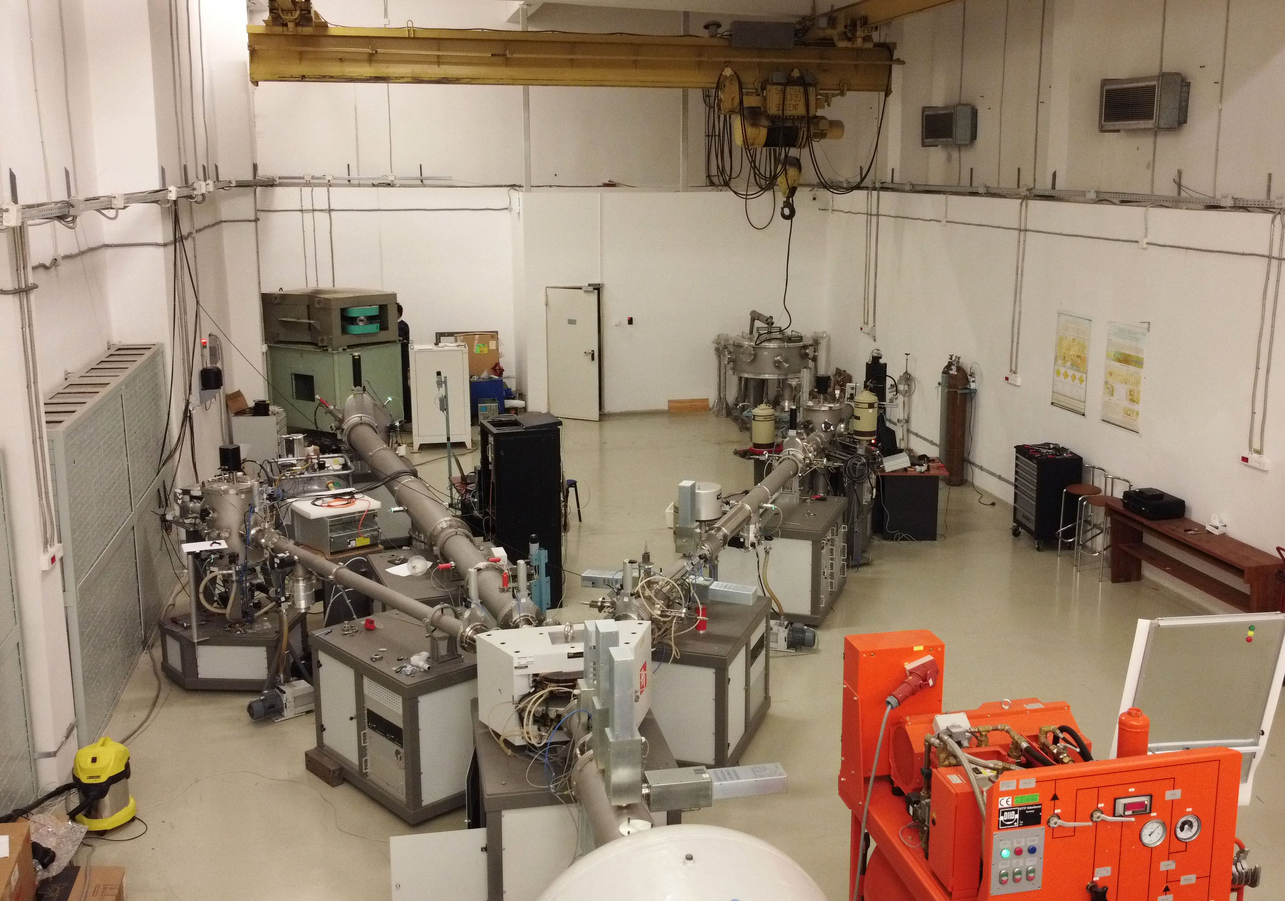
System details & layout
Beam-line geometry and the subsystems behind it — injectors, acceleration, beam transport, and experimental stations
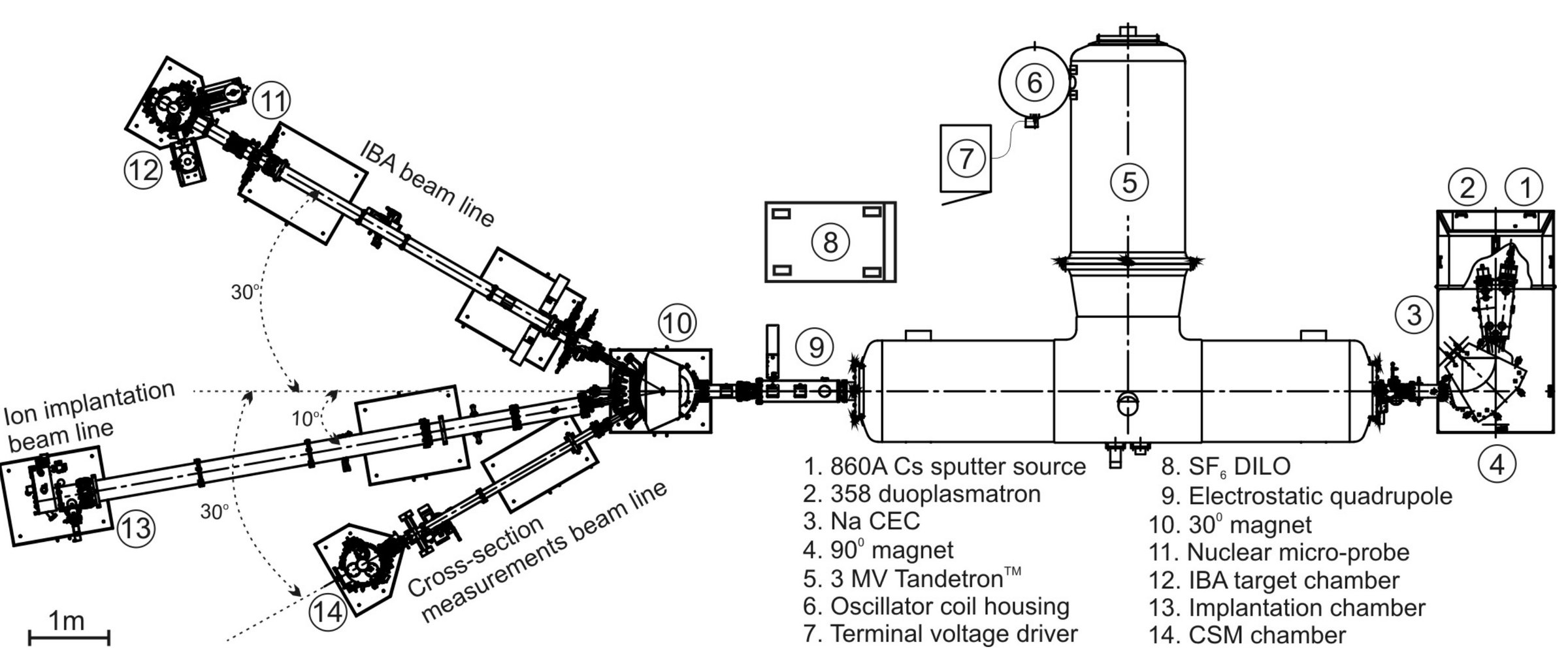
- 1. 860A Cs sputter source
- 2. 358 duoplasmatron
- 3. Na CEC (charge exchange canal)
- 4. 90° magnet
- 5. 3 MV TandetronTM
- 6. Oscillator coil housing
- 7. Terminal voltage driver
- 8. SF6 DILO
- 9. Electrostatic quadrupole
- 10. 30° magnet
- 11. Nuclear micro‑probe
- 12. IBA target chamber
- 13. Implantation chamber
- 14. CSM chamber
1. Dual ion injector
Negative sputter ion source with Cs (model 860A)
- Extraction electrode
- Manual vacuum valve
- Einzel electrostatic lenses
- Electrostatic Y‑deflector
Duoplasmatron ion source (model 358)
- Extraction electrode
- Sodium charge‑exchange canal (Na CEC)
- 90° analysing magnet
Sodium furnace for neutral exchange processes.
2. T‑shaped Tandetron for medium beam currents
- Q‑snout electrostatic lens
- Pressurized vessel and acceleration column
- Resistive voltage divider
- Gas stripping canal (Ar) with recirculation
- Extraction electrode; carousel for carbon stripping foils
Tandetron‑type high‑voltage generator for medium‑current beams.
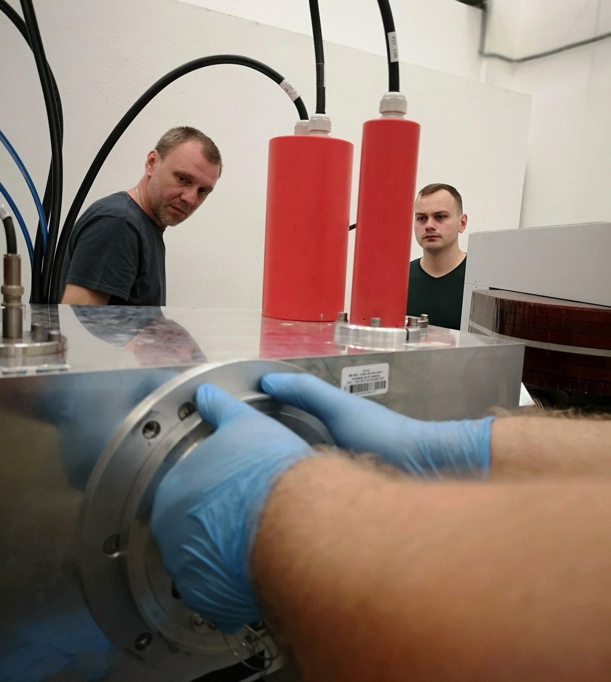
3. High‑voltage generation and control
- HV multiplier and rectifier
- Stabilization and control with GVM (Generating Voltmeter)
- Capacitive load handling system
4–6. Shielding and beam optics
- Bremsstrahlung radiation shield
- Set of three electrostatic quadrupoles
- Switching/deflector magnet with 10°, 20°, 30°, 45° ports; polarity‑reversible PSU; 0° Faraday cup
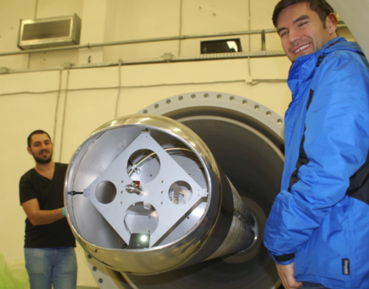
7. IBA beam line and reaction chamber
- Micrometric image and object slits (X & Y)
- X‑ and Y‑electrostatic deflectors
- Electrostatic quadrupole for micro‑beam applications
- Electro‑pneumatic Faraday cup and BPM monitoring
- Cylindrical chamber (h ≈ 500 mm, φ ≈ 400 mm)
- 4‑axis motorized target stage
- Charged‑particle detectors: fixed 165° and mobile 10°–150°
- Electronics: preamp, spectroscopy amp, HV supply, DAQ (MCA FastCom/MPANT), NIM rack
- CCD video camera (×7), LN2 trap
- Foil carousel (ERDA), retractable SDD (PIXE), retractable HPGe (PIGE)
- In‑air extraction with automated XYZ target support (radiobiology, in‑air PIXE)
8. Implantation / irradiation beam line
- Electrostatic beam sweep 17×17 cm
- BPM with four Faraday cups and secondary‑electron suppression
- Manual sample carousel
- Sample holder heated up to 800 °C and LN2 cooled option
- Beam stop
9. Cross‑section measurements (CSM) beam line
- Cylindrical chamber (h ≈ 500 mm, φ ≈ 400 mm)
- Fixed target mount; mobile detector arm (10°–150°)
- 11 ports, collimation system, and two Faraday cups
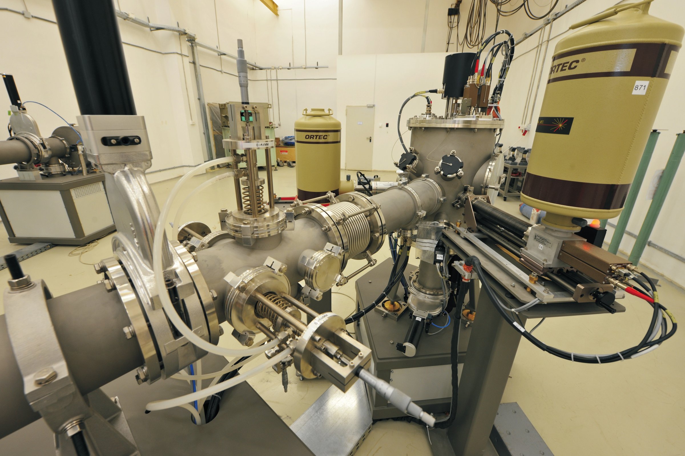
What it measures & produces
IBA, implantation/irradiation, and cross‑section measurements
IBA studies
Charged‑particle detectors for Rutherford backscattering spectrometry (RBS) and elastic recoil analysis (ERDA); SDD detectors for X‑rays used in particle‑induced X‑ray emission (PIXE); high‑purity germanium (HPGe) detectors for γ‑ray spectroscopy (PIGE); and a Markus ionisation chamber for dosimetry in radiobiology experiments. On crystalline samples the same charged‑particle detectors run RBS in channelling mode (RBS/C): the 4‑axis target stage aligns a lattice axis with the beam, so most ions channel straight through and the backscattered yield measures lattice disorder, defect depth profiles and the recovery of radiation damage. The IBA line also includes a set of four electrostatic quadrupoles, enabling micro‑beam focusing to micrometer‑scale diameters.
Implantation / irradiation
Electrostatic ion‑beam scanning in XY over 17×17 cm with four Faraday cups for fluence measurement accurate to within 2%.
Cross‑Section measurements (CSM)
A flexible multi‑purpose beam‑line that can be equipped with HPGe and Si detectors, a collimation system, and Faraday cups to optimise ionic optics and precisely determine beam current.
The line is configured to measure how nuclear reaction probabilities vary with beam energy — cross-sections of nuclear-astrophysics interest that feed models of stellar nucleosynthesis and reaction networks.
Research it powers
How the 3 MV Tandetron connects to DFNA's research directions
Access, services, and visits
Material analysis for professionals and outreach for education
Material analysis with the 3 MV beam
Professionals from academia, cultural heritage institutions, hospitals, and industry are welcome to contact us to discuss material analysis using the 3 MV Tandetron. The facility is particularly well suited for archaeological samples (e.g. pigments, metals, ceramics) and radiopharmaceutical applications (target characterisation, activation studies), but can also support a wide range of other civilian applications where ion‑beam methods bring added value.
Together with our team, we can help you identify the most appropriate technique (IBA, implantation/irradiation, or cross‑section measurements), design a feasible measurement plan, and evaluate experimental time and constraints. For enquiries and collaboration proposals, please use the contact details provided on the Contact page.
Visits for schools and universities
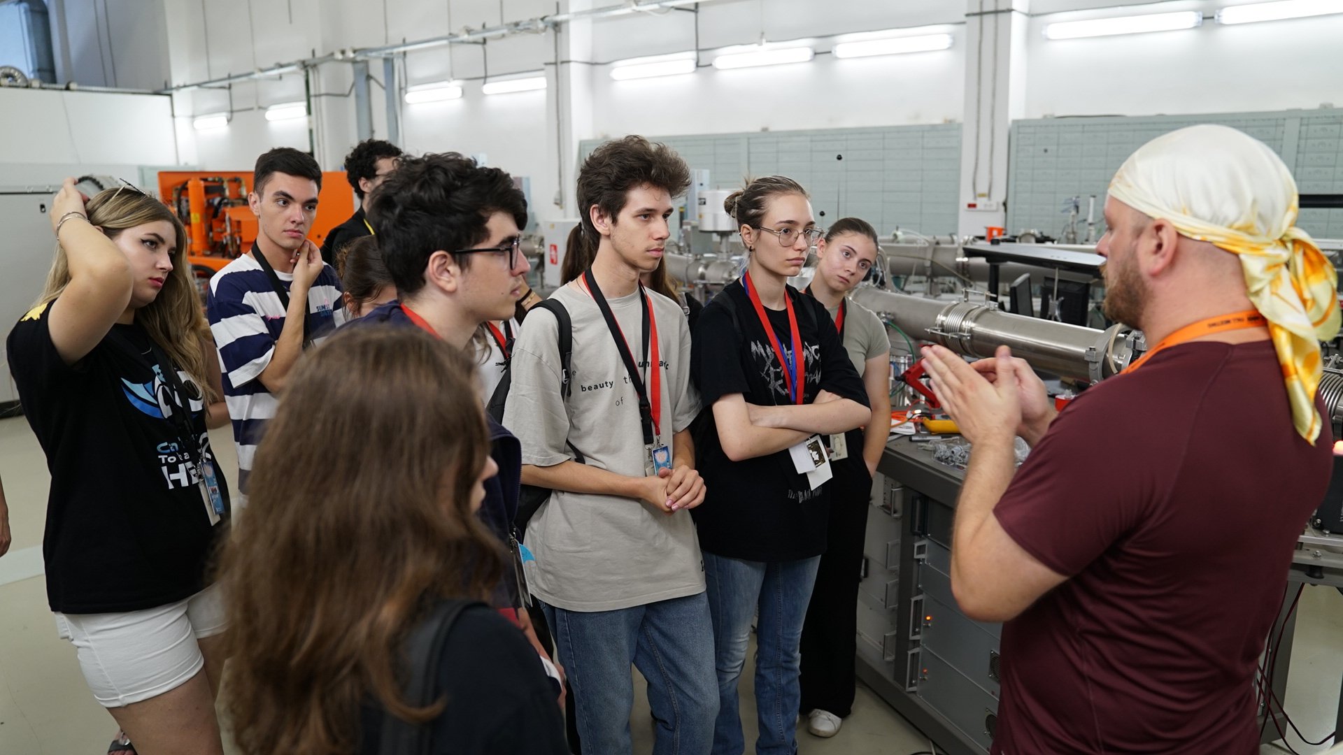
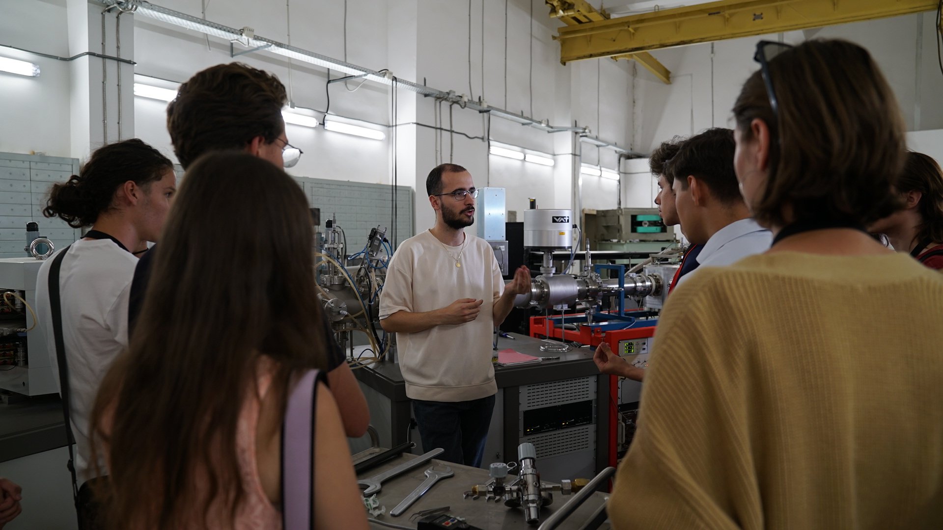
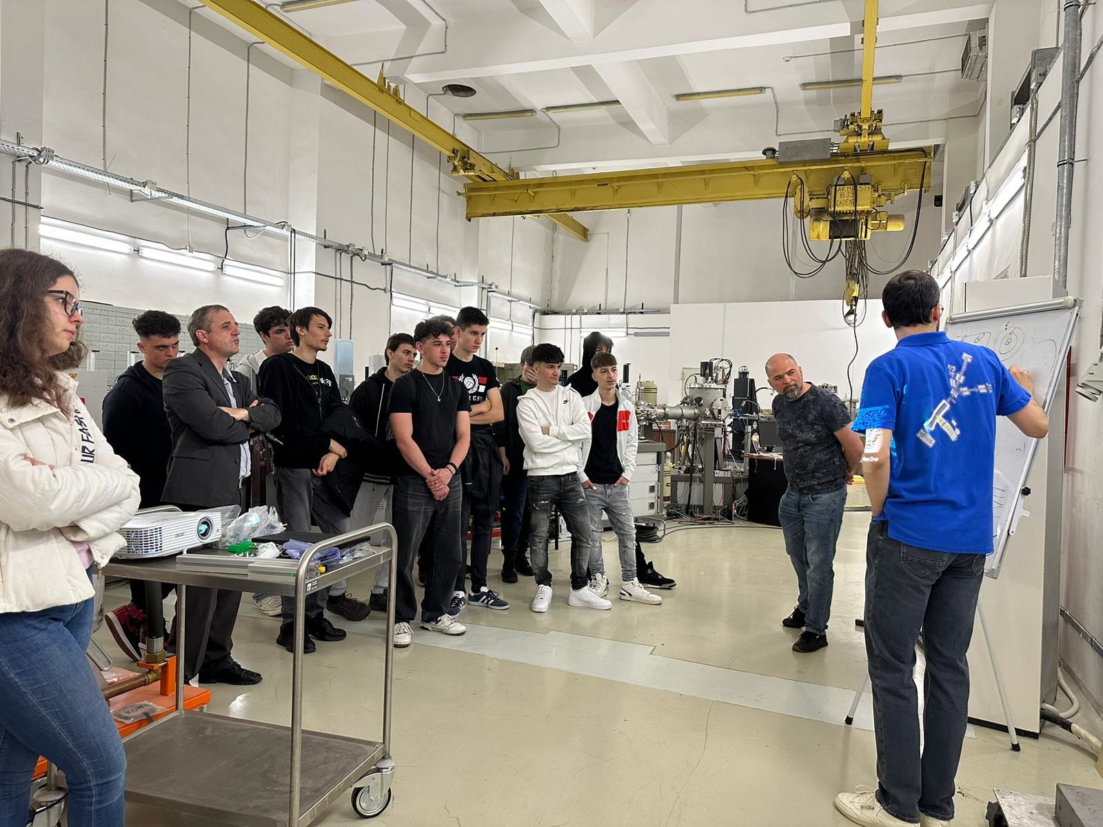
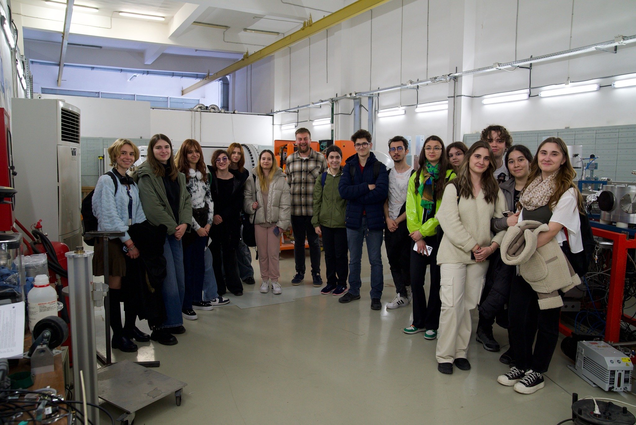
We regularly host guided visits for schools and universities who wish to see the 3 MV Tandetron and learn how ion‑beam technologies are used in research and applications. Several visits have already taken place, and we are always happy to share our knowledge with younger generations and inspire future researchers.
Visits can be organised throughout the year by prior arrangement. For the Romanian „Școala altfel” programme, places can be limited, so we strongly recommend that teachers and coordinators apply well in advance via the Contact page.
Gallery
Snapshots from lab tours and outreach events
Try it yourself
A virtual control desk for the 3 MV Tandetron
Pump the beam line down, bring the terminal up to voltage, tune the analysing and switching magnets, and record a Rutherford backscattering spectrum of a sample — the same sequence our operators follow, driven by the same physics.
Enter the control room