Ion creation in the ECR source
Plasma from the ECR ion source is a mixture of ions, electrons and neutral particles that are in motion, colliding with each other. Several ionizations take place in the plasma chamber, all electrically charged particles (electrons and ions) interact and generate the plasma of the ion source. The A+ ions are extracted from the produced plasma with the help of a positive electric potential that expels the A+ ions from the plasma chamber separating them from the plasma electrons, leaving them in the plasma chamber. Low-energy electrons (cold electrons) can leave the plasma chamber of the source faster than ions because the electrons have greater mobility. [4] The positive electric potential applied to the ECR plasma chamber maintains neutrality, reducing low-energy electron losses by confining them to an electrostatic field. The electric potential applied to the plasma chamber was determined following the studies, depending on the operating parameters of the source, having values in the range of 10-50kV. Fig. 3 The helical trajectory of electrons in the plasma chamber
Obtaining high energy electrons
Electrons in the ECR plasma follow helical trajectories along magnetic field lines. The frequency of local rotation around these lines of motion is described by equation (2.7), in the case of its adaptation for the electron it follows that:Ωe=eB⁄me (2.8)
Microwave system
The microwave generation system called KHPA-14 (Klystron High Power Amplifier) can provide microwaves with an easily adjustable frequency in the 14-14.5 GHz range, the generated frequency coincides with the resonant frequency in the electron velocity distribution at a magnetic field Bmin of about 1.2 T. The microwave generator is a Klystron tube also used as an amplifier. The microwave injection power into the plasma chamber is between 250-500 W, this being controlled by the operator in the built-in computer of the microwave system. The value of the injected power in the system is carefully controlled, continuously measuring the reflected power, which shows if the electrons do not absorb the injected power, this being reflected back by the walls of the plasma chamber. Under normal operating conditions the value of the reflected power must not exceed 2-3% of the injected power.Vacuum system
To ensure a minimum of interaction of the ion beam with the rest of the atoms in the enclosure, a high vacuum level must be ensured throughout the installation at certain key points. The vacuum system can be divided into two categories, the preliminary vacuum system and the advanced vacuum system. Both systems consist of 4 vacuum pumps, the preliminary vacuum is provided by mechanical pumps up to a value of about 10-3 mbar, and the advanced vacuum is made with turbomolecular pumps up to a value of about 10-7 mbar. The vacuum control is done through the special control modules with inverter, and its pressure measurement is performed with pirani pressure gauges for the preliminary vacuum and penning type gauges for the advanced vacuum.Injection system of Cu atoms into the plasma chamber of the ECR source by sputtering
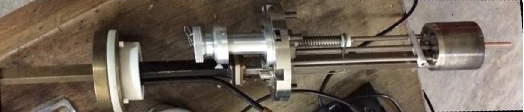
For the introduction of Cu atoms inside the plasma chamber of the source, the sputtering method was chosen because it allows the introduction of a large number of Cu atoms in the plasma thus obtaining a current of the obtained ion beam, satisfying the implantation requirements, also the sputtering method. can easily control from the operator's computer. A great advantage to make possible the implementation of this method is the fact that the changes inside the plasma chamber of this ECR source were minor, in other words it can be said that the source was prepared from its conception, for the implementation of a system of sputtering.
The principle underlying the method of obtaining Cu atoms by sputtering is the introduction into the plasma chamber of a copper bar (of high purity) and its placement at an electric potential relative to the plasma in the chamber, so that some of the Argon ions (obtained after ionization of the main gas Ar introduced into the plasma chamber) to be attracted by the Cu bar, hitting it with speed, following the mechanical interaction being expelled Cu atoms in the plasma chamber of the source in order to ionize them. Figure 4 describes the principle of sputtering with Ar ions in a target.
From a technical point of view, a high voltage source with floating potential was used to implement this sputtering technique, because the plasma chamber of the ECR installation is raised to an electric potential of the order of tens of kV + 10kV to + 35 kV used for ion extraction.